-KNOSSOS-

Thursday, November 03, 2005

a few sketches


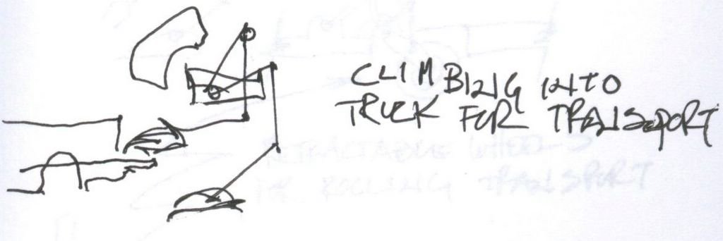
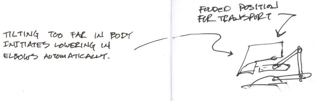
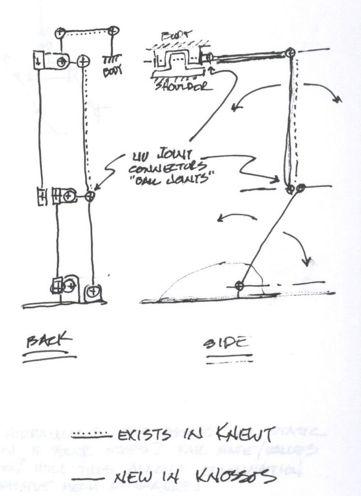
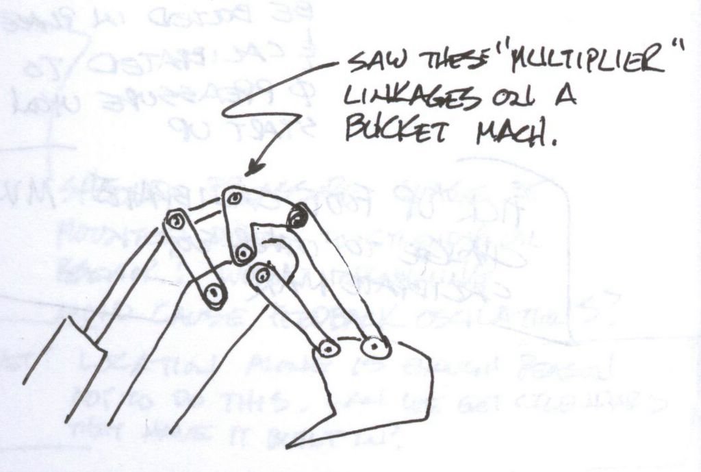
While on vacation I managed to sketch of few ideas concerning the scaling up of Knewt. This image shows an extra joint at the top right. In order to fold Knossos enough to get it into trucks for transport, this extra joint is needed. It has other advantages as well.


Self loading will allow the bot to be manageable by one person. The extra joint allows the foot to be raised higher on Knossos than on Knewt.


By automatically lowering the body when the balance sensor nears "the red", a self righting feature is inhearently available. As the center of gravity is lowered, tipping is increasingly difficult. However at full lowered position, and with foot flaps folded up on the side, a fallen Knossos could be righted by one person.


The kind of ballance sensors we've discussed are piezo gyros and accelerometers. Knewt is scheduled to recieve these in it's next phase of development. Len Harrelson of the Southern Poly Arial Robotics Group will advise on the use of these sensors. They use them to stabalize their un-manned helicopter during the IARC competition. Dale Heatherington has alot of experience with using piezo gyros in his bots. He tends to hack into the sensor and use outputs that weren't neccessarily intended to be used. Knewt will test coding scenarios of these instruments for use on Knossos.


I toyed with the idea of a self righting arm in this sketch. Some form of leverage assistance might be needed as we expect it to be over 200lbs most likely. Knewt was provided with future development space to attach an arm and Knossos provides this location as well.


This image shows from the ankle to the elbow is a 4 bar linkage just like Knewt. The elbow to shoulder part is new to Knossos. The cylinders above and below show possible actuator location to move this new section.


If we continued this 4 bar linkage experiment it might look like this. This helps with passive balance. Our experience has so far been that the passive linkages require power assistance. So the value of the extra mechanical complexity might be questioned. During power off however, it can make the difference between, relaxing to a sitting position, and falling into a random pile.


The un-sung hero of the passive balance linkage is the outrigger. The new leg joint will require an advanced outrigger. This sketch shows the foot linked through a pivot on the ankle, to a differential of sorts in the new joint. This is then carried as a rotational force through a drive shaft to the body joint. It's a little daunting.


I saw this linkage on a shovel in Spain and wondered if the multiple parts increased the power or if they had some other purpose like minimizing the arc required to fit into tight spaces. Is this usefull for powering the new joint?


There are enhancements neccessary in the foot to deal with un-even ground. The small model relies on a level surface for balance. Tables and floors provide this easily. On a large model that will be presented in parking lots, grass fields, and the like, an ability to sense and compensate for bumps and holes is neccessary. The sketch shows sensors located around the foot in opposing pairs. The feedback from these opposing pairs of pressure sensors drive actuators in the ankle to move the x,y orientation until all the sensors read the same stress, balancing the weight on the foot no matter the terrain. This would be an active sense and respond loop that updated continuously.


This idea is shows the foot articulated with hinges to reduce the wide foot print for storage and passage through narrow areas. The worm gear actuator is the beginnings of an idea to provide a second axis of control.


The unlevel ground shown here is exaggerated for illustration. Up to some mechanical limit, the actuated "toes" on the foot will calibrate themselves to the ground continuously. Flexing back and forth seeking equilibrium from the sensors. I'ld picture the central ankle/foot portion to be kept horizontal by the passive linkage with the body through the 4 bar linkages and the outriggers. The toe actuators are levered from this central foot "stage". Toes activate proportionally to pressure sensed.


The actuated side portion of the foot in the previous sketch allows for rollers to be mounted for transport. These rollers would be in-active in walking mode. As the foot sides were folded up, the wheel would be rotated into position to allow easy moving of the bot. This would be a power failure default.


This sketch explores many differnt ways the hinge configurations in the foot might be done. The bottom of the foot might be 3 or 4 different surfaces all working against the ground. Or there might be a central foot "stage" and the toes reach to the ground from there, sort of at "points" rather than big flat areas. The front to back, or side to side, orientation of the footpads will affect the programming directly. Balance sensors and "end effectors" will work in unison.


This idea ponders the possibility of equalizing the "toes" via a hydraulic or magnaferric fluid. In this scenario, upon foot fall, the toes would contour to the ground in a "floating" state as the fluid equalized around the circuit. Then, as the foot is called upon to balance and carry weight, the valves would close and the fluid become static. Now the actuators can do thier work. It's a kind of a two state machine. Passive / for quick, dynamic conformation. And active for dynamic balance.


A possible sensor for the toe / balance is a strain gage. It's a solid state device and can be located in any of several locations. Mounting it on the end of the toe might make it easy to access but leave it vulnerable to moisture and grime. I'm in favor of locating it at the other end of the actuator, near the ankle. Preassure would be read the same at either end. This sketch shows cylinder actuators but they might be worm gears or other linear electrical actuation.


This cross secion of a toe shows a strain gage installed, and how it might be captured within a bolted part.